by Hal Davis
Airport Compliance Manager
WisDOT Bureau of Aeronautics
Published in Midwest Flyer – Dec 2016/Jan 2017
In our industry, we continually strive to improve safety. While much of the focus rightly remains on in-flight safety and preventing occurrences like loss of control or controlled flight into terrain, it’s important not to overlook safety on the ground. Safely navigating the airport environment is a fundamental skill all pilots are taught from the very beginning. However, incidents, such as runway incursions, continue to pose a significant challenge. In the Great Lakes Region alone, 96 pilot deviations were reported from October 1, 2015 to September 30, 2016. Lack of airport familiarity is one of the leading causes of these types of incidents according to the Federal Aviation Administration (FAA).
At a familiar airport, it’s easy to take airport markings, lights, and signs for granted. A pilot may know which runway is which and how to get there without so much as a glance at any visual aid. In contrast, markings, lights, and signs are vital for navigating an unfamiliar airport.
Whether you are an experienced pilot, or still learning to fly, I believe it’s valuable to take a moment to review airport markings, lights, and signs, what they mean, and how they can keep you out of trouble. Over the course of the next few issues of “Aeronautics Report,” I’ll cover various airport visual aids in greater depth – starting with runway markings.
Two Common Elements
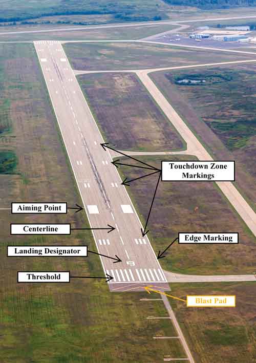 All paved runways share at least two runway marking elements. Can you name them?
The first is the runway landing designator, also known as “the numbers.” The designator is white and consists of a one or two digit runway landing designation number. As most readers probably know, the designation number is the magnetic heading along the runway centerline when viewed from the direction of the approach, rounded to the nearest one-tenth of the magnetic azimuth. For example, a runway with a magnetic heading of 173° would receive a designator of 17, while a runway heading of 178° would receive a designator of 18.
For parallel runways, each runway landing designator number will be accompanied by a letter, in order from left to right when viewed from the direction of the approach. Letters include “L” for left, “C” for center, and “R” for right. Should an airport have more than three (3) parallel runways, additional runway designators are rounded to the next nearest one-tenth of the magnetic azimuth and given a letter (e.g. 18L, 18R, 19L, 19R).
The second runway marking element shared by all paved runways is the runway centerline. The centerline identifies the physical center of the runway width allowing for alignment during takeoff and landing. The centerline is marked by white uniformly spaced stripes.
Runway Marking Schemes
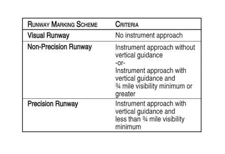
Whether or not a runway has any additional markings depends on a few factors, but the most significant factor is related to the type of instrument approach available on a particular runway. The table below lists the three runway marking schemes and the criteria for each:
Many visual runways are only required to have a designator and centerline markings. However, visual runways serving aircraft with final approach speeds greater than 120 knots are also required to have threshold markings. Threshold markings help pilots identify the beginning of the runway. Threshold markings are located 20 feet from the physical start of the runway threshold and consist of a pattern of white, longitudinal stripes spaced symmetrically about the runway centerline. All non-precision and precision runways are also required to have threshold markings.
 All precision runways, as well as visual and non-precision runways over 4,200 feet long, are also required to have aiming point markings. As you can probably guess, the aiming point markings serve as a visual aiming point during landing. Under normal circumstances, the aiming points are located 1,020 feet from the runway threshold and are marked by two white rectangles located symmetrically on each side of the runway centerline.
There are three general runway marking schemes – visual, non-precision and precision. The touchdown zone markings on this runway mean this is a precision runway.
Finally, runway edge markings are also required for all precision runways or for any other runway when the full runway pavement width is not available for use as a runway. The runway edge marking consists of a continuous white stripe with the outer edge of each stripe approximately on the edge of the paved useable runway.
Displaced Thresholds & Aligned Taxiways
Many airports have paved surfaces aligned with the runway, which may or may not be used for different phases of flight. Knowing the difference will not only save you from embarrassment, but could also save your life.
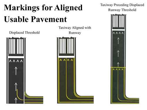
Perhaps one of the most common runway markings that adds a bit of complexity is the “displaced threshold.” A displaced threshold is a threshold located at a point along the runway other than the physical beginning of the runway. Typically, a threshold is displaced for obstacle clearance reasons on approach. Therefore, the portion of runway prior to the displaced threshold is unusable for landing. However, the area may be used for takeoff in either direction or landing rollout from the opposite direction.
A displaced threshold is marked by a white, 10 ft. wide threshold bar across the width of the runway. White arrows are also located along the centerline in the area between the beginning of the runway and the displaced threshold.
In other cases, the aligned pavement preceding a threshold may be unusable for landing and takeoff, but is available as a taxiway. Accordingly, this area is painted differently than a displaced threshold. Where the aligned taxiway abuts useable runway, yellow arrowheads spanning the width of the pavement are used along with a painted bar. A yellow bar, known as a demarcation bar, indicates the beginning of a runway with a displaced threshold, while a white bar indicates the runway threshold.
Chevrons & X’s
Often, airports will install pavement adjacent to the runway, which is unusable for aircraft operations. These areas typically serve one or two purposes.
First, the area may act as a “blast pad,” protecting the surrounding area from erosion caused by engine blast. Second, it may act as a “stopway.” A stopway is an area beyond the runway end able to support an airplane during an aborted takeoff, without causing structural damage to the airplane. Similarly, an “engineered materials arresting system” (EMAS) is designed to stop an overrunning aircraft by absorbing the aircraft’s energy as it reliably and predictably crushes under the weight of the aircraft. Blast pads, stopways, and engineered materials arresting systems are all marked by large yellow chevrons spanning the width of the pavement.
Similar in purpose to a blast pad, airports, which serve large jet traffic, may also construct runway shoulders to further reduce erosion caused by engine blast. Accordingly, airports may choose to further differentiate the shoulder from the runway by painting runway shoulder markings. Runway shoulder markings are located every 100 feet between the runway edge marking and the edge of the pavement. They are yellow in color and are slanted at a 45° angle from the runway centerline.
Lastly, from time to time, you may come across a closed runway. Airports have two options for visually conveying a closed runway to pilots. The first option, and FAA’s preferred method, is to display a raised-lighted “X” on each end of the runway. Alternatively, an airport can place a large yellow “X” over the runway landing designator. Because many runway closures are temporary, these markings may or may not be painted. Instead, a more easily removable material is often used. Of course, a Notice to Airman should always accompany any visual que that a runway is closed.
Looking For More Information?
Watch for the next issue of “Aeronautics Report” where we will take an in-depth look at more airport markings. In the meantime, information about airport pavement markings can be found in Chapter 2 of the FAA’s Aeronautical Information Manual or Advisory Circular 150/5340-1L.

