by Hal Davis
Airport Compliance Manager
WisDOT Bureau of Aeronautics
Published in Midwest Flyer – February/March 2017 issue
The last Aeronautics Report kicked off a series of articles focused on airport visual aids and provided an overview of runway markings. In this issue, I’ll be covering taxiway markings and nearly every other marking you may come across on an airport. Have you seen them all?
The Basics
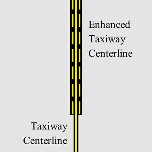 While all runways share two common markings (the centerline and designator), a taxiway is really only guaranteed to have one, the centerline. The centerline, of course, is a continuous yellow line located along the center of the taxiway. In most circumstances, aircraft are expected to remain centered over the taxiway centerline unless obstacle avoidance dictates otherwise. At some airports, including all airports serving commercial airlines, the 150 feet prior to the runway holding position marking is marked as an enhanced runway centerline, which consists of the normal yellow runway centerline as well as two additional yellow dashed lines on each side of the centerline. The purpose of the enhanced centerline marking is to provide an additional visual cue to pilots that they are approaching a runway to help prevent runway incursions.
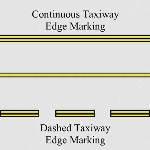
Taxiway edge markings are used to define the edge of the taxiway from other pavement. Depending on whether or not the adjacent pavement is intended for aircraft use, the edge marking is either continuous or dashed. A continuous, double yellow edge stripe indicates that the taxiway edge should not be crossed. A dashed, double yellow edge stripe indicates that the adjacent pavement is intended for aircraft use and can be crossed. For example, a no-taxi island will be bordered by a continuous taxiway edge marking, while a dashed taxiway edge marking would be used to denote a taxi route along the outer edge of an apron.
Like runways, taxiways and aprons may be outfitted with paved shoulder areas to prevent erosion from jet blast or stormwater. Normally, a continuous taxiway edge marking is all that’s needed to differentiate the usable pavement from the shoulder, but in cases where it is less obvious, a taxiway shoulder marking is used. Taxiway shoulder markings are yellow in color and run perpendicular to the taxiway centerline. In addition, some airports choose to further differentiate unusable pavement from usable pavement by painting the unusable areas green.
Holding Position Markings
Holding position markings play a vital role in keeping aircraft adequately separated at intersections and other safety critical areas. There are five locations where holding position markings may be found on airports. Knowing where to expect a holding position marking and what each means will undoubtedly aid a pilot’s situational awareness while operating in the airport environment.
Runway Holding Position Markings On Taxiways
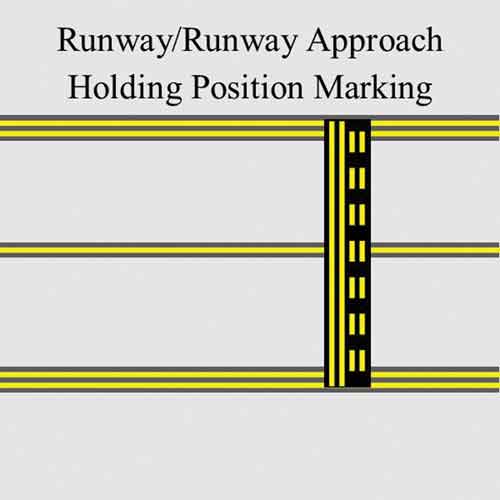
The first, and by far the most common location, is on a taxiway at the intersection with a runway. These runway holding position markings act as the border between taxiway and runway. At an airport with an air traffic control tower, a pilot may not cross the runway holding position marking until cleared to do so by the air traffic controller. At an airport without an air traffic control tower, pilots are expected to stop at this location until they have adequate separation with other aircraft before proceeding onto the runway.
Runway Holding Position Markings On Runways
Runway holding position markings can also be found on intersecting runways whenever that runway is used for land and hold short operations or when occasionally utilized for taxi operations. In either case, the runway holding position marking denotes where an aircraft is to stop and hold for clearance before crossing the intersecting runway.
Runway Approach Area Holding Position Markings
In some instances, a taxiway may not intersect with the runway itself, but instead, intersect with a runway approach area or the runway safety area. Accordingly, it may be necessary for aircraft to hold on the taxiway as to not interfere with departures or arrivals to the nearby runway. Unlike the holding position markings for intersecting runways, runway approach area holding position markings may be crossed unless instructed to hold short by air traffic control. If the airport is uncontrolled, pilots are expected to verify they have adequate separation from other air traffic before proceeding into the runway approach area.
Runway and runway approach area holding position markings consist of four yellow parallel lines, two solid and two dashed, spanning the width of the taxiway or runway. The solid lines are always on the side where the aircraft is to hold. For a perpendicular intersection, the location of the runway holding position marking ranges from 125 feet to 280 feet from the centerline of the intersecting runway. The distance depends on the approach speed and wingspan of the aircraft for which the runway was designed. For runways designed for larger and/or faster aircraft, the runway holding position markings are located farther away, creating a larger safety buffer.
When instructed to hold short of a runway, no part of the aircraft may extend beyond the holding position marking. Conversely, an aircraft exiting the runway is not clear of the runway until all parts of the aircraft have crossed the holding position marking.
ILS Critical Area Holding Position Markings
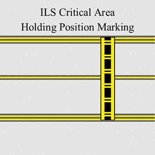
Instrument Landing Systems (ILS) depend on a reliable, accurate transmittal of radio signals from the localizer and glideslope equipment on the ground to the aircraft on approach. To protect against signal interference, ILS critical areas are cleared of all physical obstructions (including aircraft) when the equipment is in use. Often, ILS critical areas overlap taxiways and other paved areas. An ILS critical area holding position marking is used to identify the boundary of the ILS critical area. Pilots are expected to stop so no part of the aircraft extends beyond the marking whenever instructed to hold short of the ILS critical area by air traffic control or if the ILS is in use at an uncontrolled airport.
The ILS critical area holding position marking consists of two solid parallel lines, which follow the boundary of the ILS critical area. These lines are spaced four feet apart (two feet at some smaller airports) and are connected perpendicularly by sets of two lines that are spaced one (1) foot apart and repeat every 10 feet roughly resembling a ladder.
Taxiway Holding Position Markings
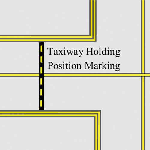
At airports with an air traffic control tower, taxiway holding position markings are often utilized anywhere aircraft are normally requested to hold, other than on or at a runway. For example, a busy intersection between two taxiways, or the boundary between a holding bay and a taxiway. A taxiway holding position marking consists of a single dashed yellow line. Pilots are expected to hold short of this marking as instructed by air traffic control. If no marking is present, a pilot should stop the aircraft at a point, which provides adequate clearance from other aircraft.
Surface Painted Signs
Surface painted signs come in a variety of shapes, sizes and colors. For the most part, they exist to supplement a nearby sign. Nonetheless, surface painted signs provide yet another defense against loss of situational awareness and runway incursions.
Surface Painted Holding Position Signs
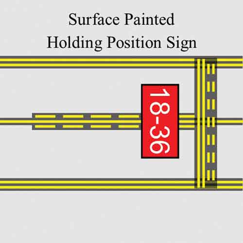
In 2010, FAA made surface painted holding position signs mandatory at all commercial service airports in an effort to further combat runway incursions and wrong runway takeoffs. By essentially copying the holding position sign to the pavement, pilots are provided yet another visual cue that they are approaching a runway. Surface painted holding position signs feature white numerals displaying the runway designators on a red background. At an intersection with multiple runways, white arrows are also used. Depending on the width of the taxiway, a single surface painted holding position sign may be positioned centered over the taxiway, on the left side of the centerline, or on both the left and right sides of the taxiway centerline.
Surface Painted Taxiway Direction & Location Signs
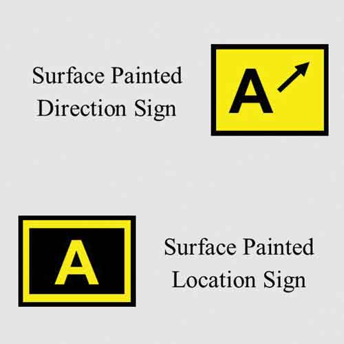
Surface painted taxiway direction signs have a yellow background with a black inscription that includes a directional arrow. These markings are used to provide directional guidance at taxiway intersections whenever it is impossible to install a normal taxiway directional sign or when a particularly troublesome intersection requires supplemental directional guidance to reduce pilot confusion. Markings indicating a left turn are painted left of centerline, while markings indicating a right turn are painted right of centerline.
Surface painted location signs have a black background with a yellow inscription. When necessary, these markings are used to supplement location signs to assist pilots in confirming which taxiway they are on. Surface painted location signs are painted right of the taxiway centerline.
Non-Movement Area Boundary Markings
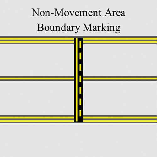
Non-movement area boundary markings identify the area of the airport under air traffic control, also known as the movement area, from those areas not under air traffic control or the non-movement area. These markings consist of two yellow lines, one solid and one dashed. The solid line is positioned on the non-movement area side. Pilots are expected to contact the air traffic control tower for taxi instructions prior to passing over the non-movement area boundary marking.
Geographic Position Markings
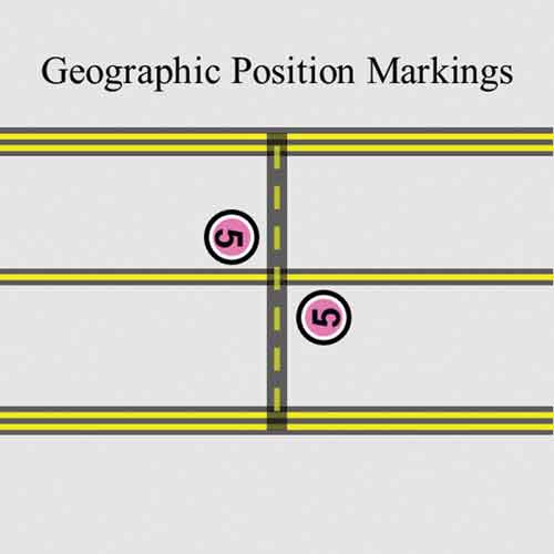
Some airports utilize a surface movement guidance control system plan to allow for low visibility taxi operations when runway visual range is less than 1,200 feet. As part of this plan, geographic position markings are repeatedly painted along the designated taxi route. A geographic position marking consists of a pink circle outlined by a white ring and a black border. The circle also contains a designation, either a number or a number and letter combination, painted in black. The designation corresponds to the sequential position of the marking along the taxi route.
These markings allow pilots to more accurately make position reports to air traffic control and confirm holding spots during periods of low visibility. Accordingly, geographic position markings are co-located with a taxiway holding position marking. The markings are positioned left of the taxiway centerline in the direction of taxi.
VOR Receiver Checkpoint Markings
Very High Frequency Omni-directional Range (VOR) is a common radio-based navigational system for aircraft. Federal Aviation Regulation Part 91.171 requires VOR equipment in the aircraft to be operationally tested in the preceding 30 days before it can be used under instrument flight rules. One method of testing the equipment is to utilize a VOR receiver checkpoint at an airport. To find out which airports near you have a VOR receiver checkpoint, search the appropriate chart supplement (formally known as the Airport Facilities Directory). A list of VOR receiver checkpoints and test facilities by state can be found toward the back of the book.
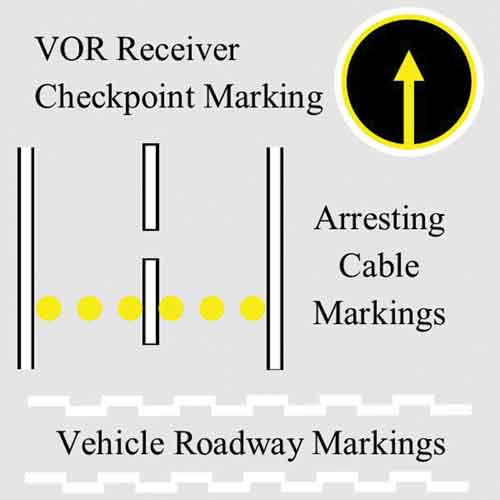
VOR receiver checkpoint markings consist of a yellow arrow aligned in the direction of the VOR facility, and is encompassed by a yellow circle. As needed the circle may be given a white border and a black interior to add further contrast. A sign is also typically associated with the marking to provide pilots with additional pertinent information for conducting the VOR receiver test.
Arresting Cable Marking
There are several runways at civilian airports in the Midwest that have arresting cables installed for military aircraft. These cables are marked by a series of 10 foot wide yellow circles spanning the width of the runway.
Vehicle Roadway Markings
Vehicle roadway markings are used to define a path for vehicles on paved areas also used by aircraft to reduce the probability of collisions. Vehicle roadway markings consist of a solid white edge line and white dashed line to delineate lanes. Alternatively, airports may choose to enhance the vehicle roadway markings by using a white and black zipper pattern in lieu of solid lines.
Find Out More
To find out more about these airport markings and a few others, check out Chapter 2 of the FAA’s Aeronautical Information Manual or Advisory Circular 150/5340-1L.
Tune in next time for a review of airport signs.
