by Hal Davis
WisDOT Bureau of Aeronautics
Published in Midwest Flyer – October/November 2017 Issue
Earlier this year, airline pilots narrowly averted disaster after mistakenly lining up to land on a parallel taxiway at San Francisco International Airport. Other pilots have made the same mistake at other airports. Fortunately, the pilots in this case realized something did not look right and initiated a go-around before it was too late. My guess is that airport lighting played a significant role in that decision.
This article is a continuation of an article on airport lights that began in the August/September 2017 issue of Midwest Flyer Magazine. In it, I covered runway and taxiway lights. This article will focus on the remaining airport lights. As the incident in San Francisco teaches us, investing a few minutes to review airport lights today may save lives in the future.
Approach Light Systems
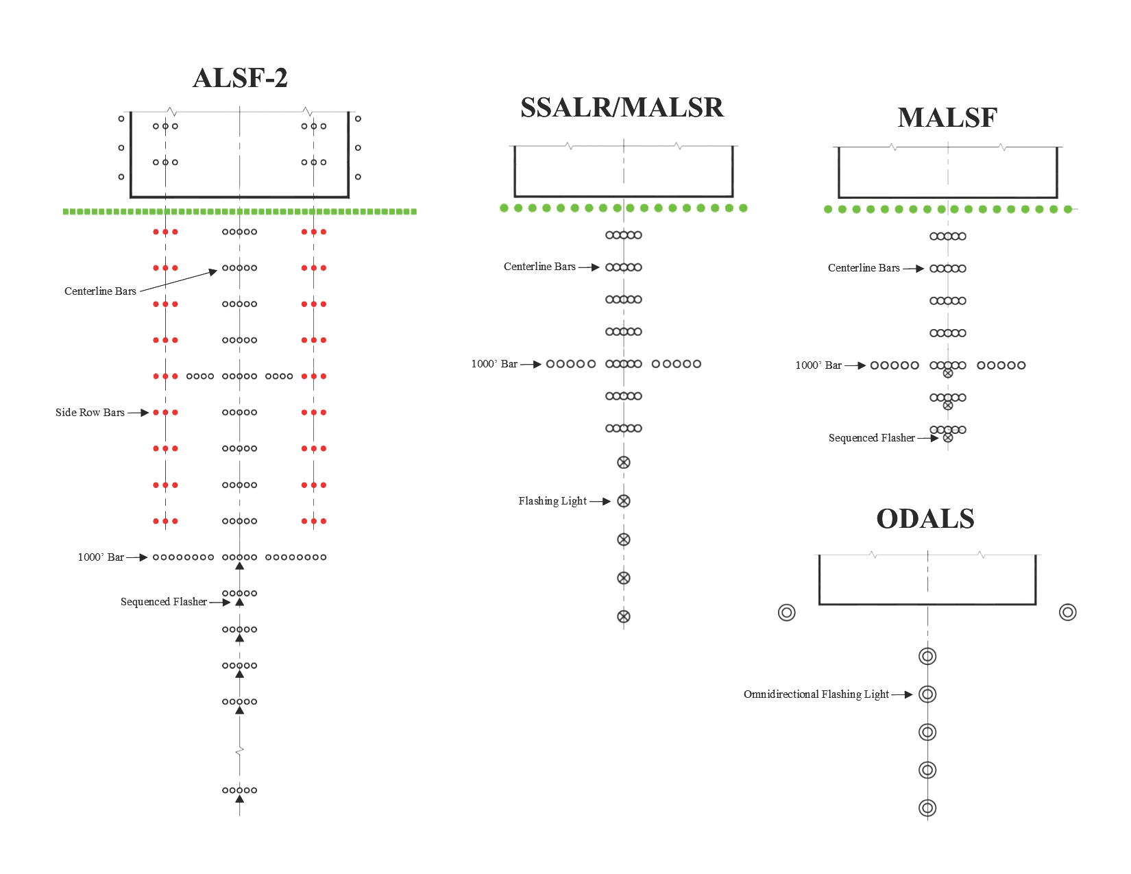
Approach light systems come in a variety of forms, but they all serve the same purpose, to assist the pilot in his transition from instrument flight to visual flight for landing. The specific approach light system relates to the type of corresponding instrument approach procedures for the runway. In general, most systems share many features.
First, a series of light bars are used to extend the runway centerline allowing pilots to align their aircraft with the center of the runway. One thousand (1,000) feet from the runway threshold, additional light bars are installed on each side of the centerline lights to create a line of lights perpendicular to the runway centerline. These lights can be used as a decision point during the approach and serves as an artificial horizon allowing pilots to roll their aircraft wings level with the runway. Beyond the 1,000-foot bar, sequenced flashers or runway alignment indicator lights are used to further illuminate the extended runway centerline.
As you might expect, runways which allow aircraft to land in the worst weather require the most precise approach procedures and the most advanced approach light systems. Currently, the most robust approach light system is the High Intensity Approach Light System with Sequenced Flashers or ALSF-2. An ALSF-2 system utilizes more lights and is of higher intensity than any other approach light systems. In addition to the centerline, 1,000-foot bar, and sequenced flashers, an ALSF-2 system also provides red row bars which essentially extend the runway touchdown zone lights.
Precision approach procedures which do not necessitate an ALSF-2 system may utilize a variety of medium-intensity or simplified approach lighting systems. Examples include:
– MALSR: Medium-intensity Approach Lighting System with Runway Alignment Indicator Lights
– MALSF: Medium-intensity Approach Lighting System with Sequenced Flashing lights
– SALS: Short Approach Lighting System
– SSALS: Simplified Short Approach Lighting System
– SSALR: Simplified Short Approach Lighting System with Runway Alignment Indicator Lights
– SSALF: Simplified Short Approach Lighting System with Sequenced Flashing Lights
In comparison to ALSF-2 systems, MALSR and MALSF systems provide much of the same information to pilots, however, they do so with fewer and less intense lights. Also, simplified systems, such as a SSALR, are not typically installed as a standalone approach light system. Rather, these systems are a subset of an ALSF-2 system and are utilized when weather conditions do not require the full ALSF-2 system to be turned on.
While all previously discussed approach light systems are designed to illuminate only in the direction of aircraft approaching the runway, Omnidirectional Approach Lighting Systems or ODALS consist of seven flashing lights which can be seen from any direction. Two lights are placed on each side of the runway threshold and the other five lights are positioned along the extended runway centerline. ODALS provide circling, offset, and straight-in visual guidance for runways with non-precision approaches.
Runway end identifier lights or REILs are installed at many airports as a more cost-effective lighting system for identifying a non-precision runway end. They are especially valuable for quick identification of a particular runway end which might otherwise be concealed by terrain or other lighting. REILs consist of a pair of synchronized flashing white lights located in line with the runway threshold and 40 feet from the runway edge.
Visual Glideslope Indicators
Visual glideslope indicators provide pilots with a visual representation of their vertical distance from the preferred glideslope. For most runways, a three-degree glideslope is used. One common example of a visual glideslope indicator is a Visual Approach Slope Indicator or VASI. While there may be slight variations in the number of lights in a VASI system, the same basic principle applies to each. A VASI consists of several light units spaced along the side of the runway. Each unit projects a white-light beam and a red-light beam. A pilot on approach to the runway will see all white lights if they are above the glideslope, or conversely, all red lights if they are below the glideslope. A combination of both red and white lights indicates the aircraft is on the glideslope.
Precision Approach Path Indicators or PAPIs work on the same principle. The primary difference between a VASI and PAPI is that PAPI lights are installed in a single row of two or four light boxes. Again, all white lights indicate the aircraft is too high, all red and the aircraft is too low, half red and half white indicate the aircraft is on the glideslope. Both VASI and PAPI lights have a range of about five (5) miles during the day and upwards of 20 miles at night.
Tri-color visual approach slope indicators are much rarer. They consist of a single light which, depending on the location of the aircraft in relation to the glideslope, appears as amber, red or green. Amber indicates the aircraft is too high, red too low, and green indicates on the glide path. These systems have a much shorter useful range than VASI or PAPI.
Pulsating visual approach slope indicators also normally consist of a single light unit. To indicate an aircraft is too high, the light pulsates white. Conversely, the light pulsates red when the aircraft is too low. Steady white indicates the aircraft is on the glide path, while steady red indicates slightly below the glide path.
Beacons
Beacons are designed to help pilots find the airport at night or possibly during inclement weather. As a result, beacons are most effective when seen from one (1) to 10 degrees above the horizon. Some beacons rotate at a constant speed, while others flash in all directions; the effect is the same. Flashes occur approximately every two (2) seconds or 24-30 times per minute. The color of the light depends on the type of landing facility.
| Type of Facility | Color Pattern of Light Flashes |
| Airport | White, Green |
| Military Airport | White, White, Green |
| Heliport | Green, Yellow, White |
| Water Airport | White, Yellow |
Normally beacons operate from sunset to sunrise. However, at airports in controlled airspace, the beacons are also operated during instrument meteorological conditions. Specifically, when visibility is less than three (3) miles or the ceiling is less than 1,000 feet.
Lighting Control
Activating airport lights, as well as controlling the intensity, is an important aspect to airport lighting. At airports with an air traffic control tower, airport lights are controlled by the air traffic control tower, although pilots may make requests. At an uncontrolled airport, and when the air traffic control tower is closed, airport lights are controlled by pilots. Pilots in the proximity of the airport can control airport lighting by tuning in a specific frequency and keying the microphone a certain number of times. Most airports utilize the local Common Traffic Advisory Frequency (CTAF), though other frequencies may be used.
Keying the mike seven (7) times within five (5) seconds will turn all airport lights on at their highest intensity. Keying the mike five (5) times within five (5) seconds will turn the lights on or lower them to medium intensity. Keying the mike three (3) times within five (5) seconds will turn the lights on or lower them to their lowest intensity. At lower intensity controls, the REILs may also turn off.
All airport lighting features for a particular airport are always controlled via the same frequency and illuminated for a period of 15 minutes from the most recent activation. There is no functionality to turn off the airport lights during this period. Finally, it is recommended to always activate airport lights at their highest setting and make subsequent adjustments as needed.
Find Out More
To find out more about airport lights, check out Chapter 2 of the FAA’s Aeronautical Information Manual (AIM), Order JO 6850.2B, or Advisory Circular 150/5340-30H.


